Categories
-
 New products (334)
 -
 Discounts (165)
 -
 Sale (70)
 -
 Measurement accessories (268)
 -
 Passive, active, waveguide RF components (25)
 -
 Vibration analysers (2)
 -
 Logic analyzers (9)
 -
 Spectrum Analyzers and EMC (224)
 -
 Automatic testing devices (6)
 -
 Luminous flux tests (2)
 -
 CNC (1)
 -
 Generators and frequency meters (97)
 -
 Calibration systems (7)
 -
 Inspection cameras and thermovision (49)
 -
 Workshop lamps (14)
 -
 Soldering irons and accessories (170)
 -
 Electronic loads - other producers (385)
 -
 Multimetry i mierniki (284)
 -
 Workshop tools (2)
 -
 Slide resistors and decades (29)
 -
 Oscilloscopes and recorders (139)
 -
 Refractometers (1)
 -
 Calibration systems, patterns (4)
 -
 Telecommunication (34)
 -
 Battery testers (4)
 -
 Device and cable testers (86)
 -
 Transformers in the housing (11)
 -
 RF power amplifiers (38)
 -
 Time patterns (1)
 -
 Power supplies of high power (298)
 -
 Laboratory power supplies (301)
 -
 Educational sets (34)
 -
 Laboratory furnitures (3)
 -
 Źródła mierzące (6)
 -
 Zasilacze DC (537)
 -
 Zasilacze AC (114)
 -
 Mierniki mocy (4)
 -
 Testery akumulatorów (5)
 -
 Systemy testujące (15)
 -
 Oprogramowanie, opcje i akcesoria (14)
News
AV1464 /A/B/C Synthesized Signal Generator
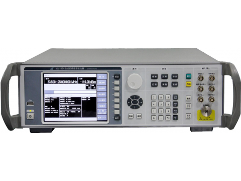

Extra-wide frequency coverage
Super pure signals
Large dynamic range high-precision power output within the bandwidth of 67GHz
High-precision analog sweep frequency output
Standard package contains an inter-modulation signal generator and a pulse generator
Excellent wideband DCFM,DCØM
High-precision linearity AM and exponential AM
High-performance pulse modulation
170GHz frequency-multiplication source module frequency extension
Analog, Step, List, and Power Sweep
Automatic software update with USB
Available models:
AV1464 (250kHz~67GHz)
AV1464A (250kHz~20GHz)
AV1464B (250kHz~40GHz)
AV1464C (250kHz~50GHz)
Frequency Range | 1464A:250kHz~20GHz. 1464B:250kHz~40GHz 1464C:250kHz~50GHz. 1464 :250kHz~67GHz.
| Frequency | N(internal YO harmonic number) | |||||||||
250kHz ≤ f ≤ 250MHz | 1/8 | |||||||||||
250MHz < f ≤ 500MHz | 1/16 | |||||||||||
500MHz < f ≤ 1GHz | 1/8 | |||||||||||
1GHz < f ≤ 2GHz | 1/4 | |||||||||||
2 GHz < f ≤ 3.2GHz | 1/2 | |||||||||||
3.2 GHz < f ≤ 10GHz | 1 | |||||||||||
10 GHz < f ≤ 20GHz | 2 | |||||||||||
20 GHz < f ≤40GHz | 4 | |||||||||||
40 GHz < f ≤67GHz | 8 | |||||||||||
Frequency Resolution | 0.001Hz | |||||||||||
Time-base Aging Rate (typical) | 5 × 10 -10 /day(power on after 30 days). | |||||||||||
Sweep Mode | Step Sweep List Sweep Power Sweep Analog Sweep | |||||||||||
Analog sweep (typical) | Max. Sweep speed rate | 250kHz ≤ f ≤ 500MHz | 25MHz/ms | |||||||||
500MHz < f ≤ 1GHz | 50MHz/ms | |||||||||||
1GHz < f ≤ 2GHz | 100MHz/ms | |||||||||||
2 GHz < f ≤ 3.2GHz | 200MHz/ms | |||||||||||
3.2GHz < f | 400MHz/ms | |||||||||||
Sweep accuracy | 0.05% Sweep width ( sweep time 100ms,within the regulated max. sweep width of 100ms) | |||||||||||
Harmonic2 | 250kHz ≤ f ≤ 10MHz | -28dBc(typical) | ||||||||||
10MHz < f ≤2GHz | -28dBc | |||||||||||
2GHz < f ≤ 20GHz | -55dBc | |||||||||||
20GHz < f ≤ 40GHz | -50dBc | |||||||||||
Sub-harmonic2 | 250kHz ≤ f ≤ 10GHz | N/A | ||||||||||
10GHz < f ≤ 20GHz | -55dBc | |||||||||||
20GHz < f ≤ 67GHz | -50dBc | |||||||||||
Non-harmonic3 | 250kHz ≤ f ≤ 2GHz | -65dBc | ||||||||||
2GHz < f ≤ 20GHz | -56dBc | |||||||||||
20GHz < f ≤ 40GHz | -50dBc | |||||||||||
40GHz < f ≤67GHz | -44dBc | |||||||||||
Single Sideband Phase Noise (dBc/Hz)4 | Frequency Freq. offset | 100Hz | 1kHz | 10kHz | 100kHz | |||||||
250kHz ≤ f ≤ 250MHz | -101 | -121 | -130 | -130 | ||||||||
250MHz < f ≤ 500MHz | -108 | -126 | -132 | -132 | ||||||||
500MHz < f ≤ 1GHz | -101 | -121 | -130 | -130 | ||||||||
1GHz < f ≤ 2GHz | -96 | -115 | -124 | -124 | ||||||||
2GHz < f ≤3.2GHz | -92 | -111 | -120 | -120 | ||||||||
3.2GHz < f ≤ 10GHz | -81 | -101 | -110 | -110 | ||||||||
10GHz < f ≤ 20GHz | -75 | -95 | -104 | -104 | ||||||||
20GHz < f ≤40GHz | -69 | -89 | -98 | -98 | ||||||||
40GHz < f ≤67GHz | -64 | -83 | -92 | -92 | ||||||||
Output power range (25±10℃) | 1464A: +13dBm ~ -20dBm With option: programmable step attenuator: +11dBm ~ -120dBm (-135dBm is settable) 1464B: +10dBm ~ -20dBm With option: programmable step attenuator: +8dBm ~ -120dBm (-135dBm is settable) 1464C/1464: +6dBm ~ -20dBm With option: programmable step attenuator: +3dBm ~ -90dBm (-110dBm is settable) | |||||||||||
Power accuracy (25±10℃) | No programmable step attenuator | |||||||||||
Freq. Power | > +10 dBm | +10~-10 dBm | -10~-20dBm | |||||||||
250kHz ≤ f ≤ 2GHz | ±1.0dB | ±1.0dB | ±2.0dB(typical). | |||||||||
2GHz< f ≤20GHz | ±1.2dB | ±1.0dB | ±2.0dB(typical) | |||||||||
20GHz< f ≤40GHz | / | ±1.2dB | ±2.2dB(typical) | |||||||||
40GHz< f ≤50GHz | / | ±1.5dB | ±2.2dB(typical) | |||||||||
50GHz< f ≤67GHz | / | ±1.8dB | ±2.5dB(typical). | |||||||||
With programmable step attenuator | ||||||||||||
Freq. Power | > +10 dBm | +10~-10dBm | -10~-60dBm | -60~-90dBm | ||||||||
250kHz ≤ f ≤ 2GHz | ±1.0dB | ±1.0dB | ±1.5dB | ±1.8dB (typical). | ||||||||
2GHz< f ≤20GHz | ±1.2dB | ±1.0dB | ±1.5dB | ±2.2dB (typical). | ||||||||
20GHz< f ≤40GHz | / | ±1.2dB | ±1.8dB | ±2.5dB typical) | ||||||||
40GHz< f ≤ 50GHz | / | ±1.5dB | ±2.0dB | ±2.5dB (typical). | ||||||||
50GHz< f ≤67GHz | / | ±1.8dB | ±2.5dB | ±3.0dB (typical) | ||||||||
Modulation | Pulse modulation | 500MHz≤f≤67GHz | Pulse modulation ON/OFF ratio | >80dB | ||||||||
Rise and fall time of pulse modulation | <20ns | |||||||||||
Min. pulse width(ALC ON) | 1μs | |||||||||||
Min. pulse width(ALC OFF) | 0.1μs | |||||||||||
AM | 10MHz<f≤50GHz | Modulation depth:>90% Modulation bandwidth(3dB,30% modulation depth, frequency point for test:1G/5G/20G/40G/50G):DC~100kHz AM accuracy(1kHz modulation rate,30% modulation depth):<±3%. AM distortion(1kHz modulation rate,30% modulation depth):<2%. | ||||||||||
FM | 10MHz<f≤50GHz | Max. Freq. offset:N×16MHz(N is harmonic number of YO). Accuracy(1kHz rate,300Hz~3kHz demodulation bandwidth,1kHz<frequency offset<N×800kHz,exclude remaining FM):<± (5%×setting frequency offset +20Hz) Modulation rate(3dB bandwidth): Internal DC:DC~100kHz;internal AC:100kHz~1MHz. External DC:DC~100kHz;external AC:100 kHz ~10MHz. Distortion(1kHz rate, frequency offset :N×800kHz,total harmonic distortion):<2% | ||||||||||
Phase modulation | 10MHz<f≤50GHz | Max. phase offset:when modulation bandwidth is 100kHz N×160rad Accuracy(1kHz rate,300Hz~3kHz demodulation bandwidth,1rad<phase offset<N×80rad,exclude remaining phase modulation,when modulation bandwidth is 100kHz):<± (5%×setting phase offset+0.01 rad) Modulation rate(3dB bandwidth): Modulation bandwidth 100kHz:DC-100kHz;modulation bandwidth 1MHz:100kHz ~1MHz(typical). Distortion(1kHz rate,1rad<phase offset<N×80rad,total harmonic distortion,when modulation bandwidth is 100kHz):<2%. | ||||||||||
Internal modulation signal generator | Function generator provides: signals of AM and freq./phase modulation Waveform: Sine wave, square wave, triangle wave, ramp wave, noise, double sine and sweep sine. Frequency range: Sine wave, double sine, sweep sine 1Hz~1MHz. Square wave, triangle wave and ramp wave 1Hz-100kHz Frequency resolution: 1Hz Pulse modulation signal: Pulse width: 20ns~(42s-10ns). Pulse cycle: 100ns~42s Resolution: 10ns | |||||||||||
RF output port | 1464A | 1464B | 1464C | 1464 | ||||||||
3.5mm(M) | 2.4mm(M) | 2.4mm(M) | 1.85mm(M) | |||||||||
Display | TFT-LCD | |||||||||||
Operation menu | Simplified Chinese/English | |||||||||||
Size (W×H×D) | Standard:426mm × 133mm × 510mm(no handles, rear feet and support). Max.:482mm × 152mm × 582mm. | |||||||||||
Max. Weight | Approx. 20kg | |||||||||||
Working temp. | 0℃ ~+40℃ | |||||||||||
Max. Power consumption | 300W | |||||||||||
Power | 220V AC | |||||||||||
Establishment of automatic scalar network testing system
1464 series can build up an auto scalar network testing system together with 36110 Scalar Network Analyzer to bring you fast and convenient wideband network test.

Multiple programming interfaces
The 1464 seriesoffers additional extended interfaces like RS232 interface, GPIB interface, network interface, etc., for your choice to enable remote control and network update.

TYPICAL APPLICATIONS
Comprehensive performance evaluation on electronic system
As synthesized signal generators with top-level performance in such field,AV1464 series can generatehigh quality analog signals in alarge dynamic rangewithin the frequency range of250kHz~67GHz. They are used in the comprehensive performance evaluation of electronic systems on radar, electronic warfare and communication equipment, etc., to address the problems in system specification test on bandwidth, sensitivity, dynamic range, intermodulationdistortion and so on.

Testing on High-performance Receiver
AV1464 series possess large output dynamic ranges and extremely high frequency stability and frequency resolution is 0.001Hz. They can output high-precision standard test signals in performance test on the high-performance receivers of radar, electronic warfare and communication equipment to address the problems in specification test on sensitivity, dynamic range, and channel selectivity and so on.

Local oscillator (LO) substitution
With high pure signal quality,the AV1464 seriescan be used as ideal local oscillators to substitute those in the equipment under test, such as transmitters and receivers. They will effectively avoid negative effect on test due to bad quality of LO so as to ensure the accuracy and creditability of your test.














 kamery do kanalizacji i rurociągów (24)
  kamery do kanalizacji i rurociągów (3)
  teleskopowe (3)
  do kominów (2)

